[单选题]
如图所示,电路原已稳定,t=0时断开开关S,则 为( )。
为( )。
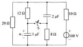 题15图
题15图
A.10V
B.15V
C.20V
D.25V
参考答案与解析:
-
相关试题
-
如图1-5-5所示,电路原已稳定,t=0时断开开关S,则<img border="0" style="width: 51px; height: 24px;"
-
[单选题]如图1-5-5所示,电路原已稳定,t=0时断开开关S,则为( )。[2012年真题]图1-5-5A.10VB.15VC.20VD.25V
- 查看答案
-
如图1-5-6所示,电路原已稳定,t=0时断开开关S,则<img border="0" style="width: 55px; height: 24px;"
-
[单选题]如图1-5-6所示,电路原已稳定,t=0时断开开关S,则等于( )。[2007年真题]图1-5-6A.5VB.25VC.10VD.20V
- 查看答案
-
如图1-5-14所示电路原已稳定,t=0时断开开关S,则<img border="0" style="width: 45px; height: 24px;"
-
[单选题]如图1-5-14所示电路原已稳定,t=0时断开开关S,则为下列何值?( )[2005年真题]图1-5-14A.78VB.117VC.135VD.39
- 查看答案
-
如图1-5-11所示,电路原已稳定,t=0时断开开关S,则<img border="0" style="width: 51px; height: 25px;&quo
-
[单选题]如图1-5-11所示,电路原已稳定,t=0时断开开关S,则等于( )。[2007年真题]图1-5-11A.5VB.25VC.10VD.20V
- 查看答案
-
如图1-5-33所示,电路原已稳定,t=0时闭合开关S后,则<img border="0" style="width: 32px; height: 24px;&qu
-
[单选题]如图1-5-33所示,电路原已稳定,t=0时闭合开关S后,则为( )。[2009年真题]图1-5-33A.B.C.0AD.
- 查看答案
-
电路如图所示,图中<img border="0" style="width: 23px; height: 24px;" src="https:/
-
[单选题]电路如图所示,图中是调零电位器(计算时可设滑动端在的中间),且已知均为硅管,,,电路的差模电压放大倍数为( )。A.-102B.-65.4C.-50
- 查看答案
-
如图所示电路中,<img border="0" style="width: 17px; height: 24px;" src="https://
-
[单选题]如图所示电路中,=0.1H,=0.15H,M=0.1H,若电源频率是50Hz,则电路等值阻抗是( )。题8图A.j31.4B.j15.7C.-j31
- 查看答案
-
<img border="0" style="width: 51px; height: 24px;" src="https://img.zhao
-
[单选题]A.-F/2B.0C.F/2D.F
- 查看答案
-
<img border="0" style="width: 51px; height: 24px;" src="https://img.zhao
-
[单选题]A.-F/2B.0C.F/2D.F
- 查看答案